stm10x_flash.icf
stm10x_flash_extsram.icf
stm10x_nor.icf
stm10x_ram.icf
如图:
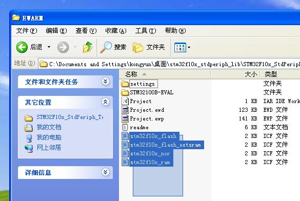
到EWARM(即放置工程文件的文件夹下),如图:
至此,所有的拷贝工作都已经完成,进入Add调整阶段。
dd以最简单的GPIO端口操作为目的,开始Add相关文件。
添加之后的结果为:
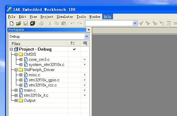
其中:
core_cm3.c是内核文件(没深入研究);
system_stm10x.c是系统相关文件(没深入研究);
misc.c是一个辅助文件;
stm10x_gpio.c是gpio的驱动文件;
stm10x_rcc.c是复位与时钟控制器驱动文件;
main.c是主程序的入口函数,是整个系统的一个主框架;
stm10x_it.c是系统的所有的中断函数文件;
至此,所有的Copy和Add操作都已经完成,接下来是Modify。
3.4 开始编译和调试 Compile with Modify首先修改main.c
修改main.c使之成为一个按照你的想法完成任务的系统功能。
最简单的任务就是:让4个LED循环亮灭;
源代码如下:
/* Includes
--------------------------------------------*/
#i nclude "stm10x.h"
/* Private prototypes
--------------------------------------------*/
void RCC_Configuration(void);
void GPIO_Configuration(void);
typedef enum {
LED1 = 0,
LED2,
LED3,
LED4,
}LED_STATE;
LED_STATE led_status;
int main(void)
{
u32 cnt = 0x000fffff;
/* System Clocks Configuration */
RCC_Configuration();
/* Configure the GPIO ports */
GPIO_Configuration();
led_status = LED1;
while (1){
switch (led_status){
case LED1:
GPIOB->BSRR = 0x1000E000; /* turn on LD1 */
led_status = LED2;
break;
case LED2:
GPIOB->BSRR = 0x2000D000; /* turn on LD2 */
led_status = LED3;
break;
case LED3:
GPIOB->BSRR = 0x4000B000; /* turn on LD3 */
led_status = LED4;
break;
case LED4:
GPIOB->BSRR = 0x80007000; /* turn on LD4 */
led_status = LED1;
break;
}
while(cnt--);
cnt = 0x000fffff;
}
}
/**
* @brief Configures the different system clocks.
* @param None
* @retval : None
*/
void RCC_Configuration(void)
{
/* Setup the microcontroller system. Initialize the Embedded Flash
Interface, initialize the PLL and update the SystemFrequency variable. */
SystemInit();
/* GPIOA clock enable */
RCC_APB2PeriphClockCmd(RCC_APB2Periph_GPIOB, ENABLE);
}
/**
* @brief Configure the GPIOD Pins.
* @param None
* @retval : None
*/
void GPIO_Configuration(void)
{
GPIO_InitTypeDef GPIO_InitStructure;
/* GPIOB configuration: PB12 PB13 PB14 PB15 as led controller */
GPIO_InitStructure.GPIO_Pin = GPIO_Pin_12|GPIO_Pin_13|GPIO_Pin_14|
GPIO_Pin_15;
GPIO_InitStructure.GPIO_Mode = GPIO_Mode_Out_OD;
GPIO_InitStructure.GPIO_Speed = GPIO_Speed_2MHz;
GPIO_Init(GPIOB, &GPIO_InitStructure);
}
Compile发现问题如下:

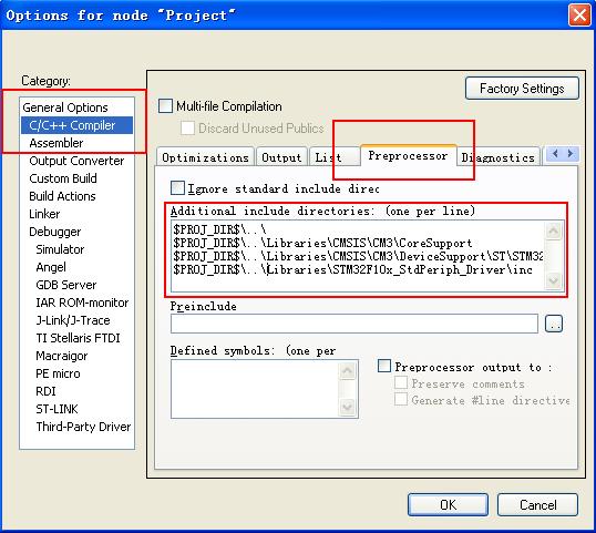
通过调整头文件路径解决:
右击Project——>option——>C/C++Compile——>Preprocessor——>:
在Additional include directories中加入如下语句:
$PROJ_DIR$\..\
$PROJ_DIR$\..\Libraries\CMSIS\CM3\CoreSupport
$PROJ_DIR$\..\Libraries\CMSIS\CM3\DeviceSupport\ST\STM10x
$PROJ_DIR$\..\Libraries\STM10x_StdPeriph_Driver\inc
如图:
Compile:您有可能会出现以下问题:

这是需要修改stm10x.h文件中的相关,因为你没有为你的芯片选择类型,点击错误,即打开了stm10x.h头文件,如图:
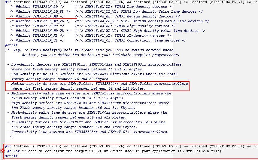
只需要选择您的期间类型就好,比如:

再Compile,这下错误出现的吓人,镇定发现,我们没有选择device type:
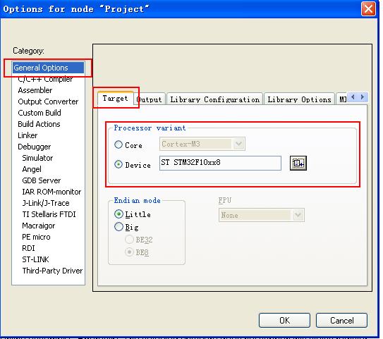
右击Project——>option——>General Options——>Target——>:
选择好正确的芯片类型,如图:






 咨询PLC培训请